How to Integrate Camera Modules Into Embedded Products
Silicon Signals Pvt. Ltd. is an Ahmedabad‑based, global R&D and product engineering firm that specializes in end-to-end embedded solutions—spanning hardware, firmware, OS/BSP, device drivers, and system integration. Trusted across industries like automotive, IoT, wearables, healthcare, and avionics, they excel in Linux, Android, QNX, FreeRTOS, Zephyr, Yocto, and more . As a recognized QNX Channel Partner and Toradex service ally, the company delivers scalable, secure, and certified embedded products—from concept through production.
The camera modules market gained 9.7% CAGR from 2025 to 2026, from $56.24 billion to $61.72 billion, respectively according to The Business Research Company. There are many industries integrating camera modules, including, but not limited to, medical and manufacturing. The integration of camera modules is becoming as important as other consideration, such as processor selection, early in the design cycle. This report provides an engineering perspective to camera module integration, from sensor selection to post production evaluation.
What Is Camera Module Integration?
There are multiple components to capturing and reproducing images. The hardware needed to take the image and the supporting circuitry need to be integrated with the processor that’s running the show. Once the hardware is integrated, the software needs to be modified in order to capture and output images the way that we want. All of these changes need to occur in order for the end product to capture and display images the way that we want.
Role of an Embedded Camera Module
An embedded camera module is comprised of a CMOS image sensor, lens, and may include an image signal processor. The module is designed to be interfaced to a printed circuit board (PCB) as opposed to be plugged into a USB port like a web camera. Thus the design engineers of the module control interfaces to the host PCB and are not dependent on USB interfaces.
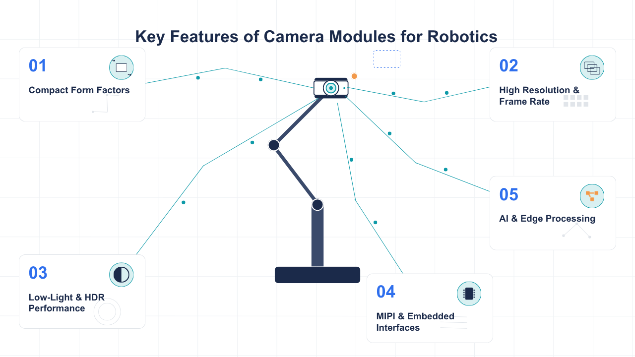
These modules are commonly used in embedded vision camera modules for industrial automation, medical equipment, smart surveillance, and AI-enabled products, where direct sensor-to-processor integration is important.
Key Elements of Camera Integration
When integrating a camera system, four things have to happen perfectly: the camera signal has to be clean, the interface carrying that signal has to be perfectly lossless, the processor has to decode the signal correctly, and the software has to transform the signal into an image. If any of these conditions are not met, image capture will either not happen, or will happen incorrectly. Capturing the wrong color is considered better than not capturing an image at all. This is why many teams that wait until the end to integrate a camera system will experience issues.
Hardware and Software Integration Requirements
Integrating a camera module is a balancing act between many teams. Often the hardware and firmware teams need to align earliest. There are several factors including the camera interface, the availability of MIPI lanes, the presence of an ISP, and the availability of sensor driver software. The layout of the PCB is usually finalized before bring-up, and changing the sensor after the PCB layout means a respin. Therefore, architectural decisions should be made before bringing up the system.
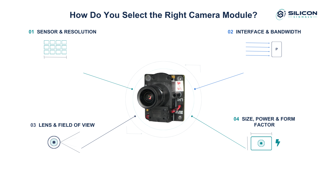
How Do You Select the Right Camera Module?
When choosing a camera module, there are many factors other than resolution that must be taken into account, including the connection between the sensor and processor, as well as the lenses and other optics.
Sensor Resolution and Image Requirements
Resolution is determined by the aspects of a product that a given application must identify or quantify. A barcode reader and a facial recognition unit would require different resolution cameras since barcodes are made up of different elements than a human face. More resolution adds more data captured in each frame, thus increasing the load on the peripheral elements of the system (like the interface) and the processor. Greater resolution leads to greater overall system complexity.
Interface and Bandwidth Requirements
The output interface of a sensor depends on the acceptance criterion of the target processor. The sensor bandwidth should be enough to support the required resolution and frame rate. A sensor that can capture 4K videos at 30 frames per second will require MIPI CSI-2 with sufficient number of lanes and a high enough clock speed to support the data transfer. The processor ISP should be able to support real time processing of that data or else, the sensor output resolution or frame rate should be restricted.
Lens and Field of View Considerations
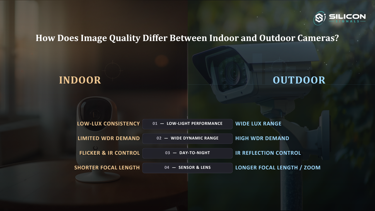
Most of the tradeoffs in a camera module are around the lens. Field of View, depth of field, and how a lens handles different lighting conditions are determined by the lens. A wide FoV lens can introduce distortion which needs to be corrected in software. This adds load to the processing unit. Mechanical design can also be impacted. A fixed focus lens simplifies mechanical design but limits the lens's abilities. This is not ideal if the lens is being used to scan or inspect documents.
Size, Power, and Form Factor Constraints
Embedded products often have strict mechanical budgets, and the camera module has to fit within them without compromising thermal performance. Power draw from the sensor and any onboard ISP affects battery life in portable designs, and module height affects enclosure design. These constraints usually narrow the sensor shortlist before image quality is even evaluated.
What Hardware Is Required for Camera Integration?
The hardware side of camera integration covers the interface standard, power delivery, physical connection, and confirmed compatibility between the sensor and the host processor.
MIPI CSI-2 and Other Camera Interfaces
MIPI CSI-2 is the dominant interface for embedded camera module integration because it offers high bandwidth over a small number of differential pairs with relatively low power draw. Some designs still use parallel interfaces or USB for lower-speed or off-the-shelf scenarios, but CSI-2 is standard for anything requiring higher resolution or frame rate on a custom board. Lane count and clock speed have to be confirmed against both the sensor's output spec and the processor's receive capability.
OEMs comparing MIPI and USB can also read why OEMs prefer MIPI camera modules over USB cameras for a closer look at bandwidth, power consumption, and embedded-system integration.
Power and Signal Requirements
Image sensors are very sensitive to power noise. Designs that have an unclean power supply will cause artifacts to appear in the captured image. There are a number of design practices that are considered good sensor power supply design. These include the use of: well regulated power rails, proper sequencing and decoupling of the sensor. The use of these practices is critical to ensure an image is captured stably and without noise.
Connector and PCB Design
Trace length matching, controlled impedance routing, and connector selection all affect signal integrity on high-speed camera interfaces. A flex cable connecting a remote sensor to a main board introduces additional signal loss that has to be accounted for in the design, especially at longer cable lengths or higher data rates.
Sensor and Processor Compatibility
Before committing to a sensor, the processor's supported sensor list and driver availability need to be checked. Some processor vendors publish board support packages with drivers for specific sensors already validated, which shortens development time considerably. Choosing a sensor outside that supported list means writing or porting a driver from scratch, which adds real schedule risk to camera module integration.
How Do You Integrate a Camera Module With Embedded Software?
The integration of software enables a sensor to produce video output. This software spans from the computer kernel to user space applications.
Camera Drivers and BSP Integration
An image sensor driver is typically a low-level driver that communicates with the sensor using one or more of the communication interfaces (I2C, MIPI CSI-2, SPI, etc.) A driver of this nature is implemented in the board support package of an embedded Linux system, and provides a video device to the rest of the system. In addition, the driver must be properly aligned to the sensor's register map to facilitate synchronous communication with the sensor to meet the sensor's timing constraints. This alignment is considered a challenging task during integration of a sensor.
V4L2 and Video Pipeline Configuration
Video for Linux version 2 (V4L2) is a framework to access video hardware in Linux. To resolve format and resolution mismatches between multiple components in the video processing pipeline, one needs to configure the V4L2 subsystem correctly. Only then will video frames reach the application without format or resolution mismatches.
Sensor Control and Configuration
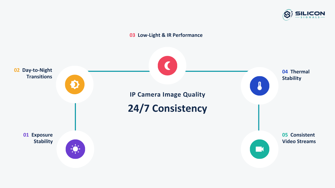
Beyond capturing frames, the software has to control exposure, gain, white balance, and focus where applicable. These controls are usually exposed through the driver and adjusted either manually or through an automatic control loop running on the processor. Getting these defaults wrong at integration time produces images that look technically correct but are unusable in real operating conditions.
ISP and Image Processing Integration
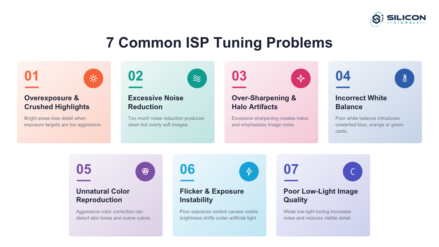
In a camera module, the ISP reduces image noise, corrects colors, and performsa process called demosaicing. All of these operations are essential to render images that are suitable for display. The ISP may be implemented in several ways. For instance, it may be implemented in software, or part of a semiconductor processing unit in a system on a chip (SoC). Regardless of implementation, it must be tuned to the specifications of the sensor and lens. Often, this step is underestimated in the integration timeline of a camera module. Resolving image quality issues is often achieved at this step.
How Do You Validate Camera Module Integration?
Integration of the camera module has been tested to ensure it functions correctly under the anticipated environmental conditions of the final product.
Image Quality and Exposure Testing
There are a number of tests to evaluate image quality including assessment of sharpness, noise, color fidelity and accuracy of exposure. All of these can be quantified with respect to the final image through the use of standard test charts. Results of these tests are helpful when defining image quality standards for different versions of a product (i.e. different sensor or firmware revisions).
Frame Rate and Latency Validation
The system has to sustain its target frame rate under real processing load, not just in a synthetic capture test. Latency from sensor exposure to displayed or processed frame matters directly in applications like robotics or driver assistance, where delayed frames translate into delayed decisions.
Low-Light and Challenging-Light Testing
How well a sensor performs in low light conditions is telling of its true character. Some mistakes like noise or motion blur become apparent in testing conditions outside the manufacturer’s controlled environment, for example in environments with low ambient lighting, or in conditions of rapid changes in lighting with or without a subject in motion.
Thermal and Long-Duration Testing
Extended operation raises sensor temperature, which can introduce noise and shift color response over time. Long-duration testing under the product's actual thermal envelope catches degradation that short bench tests miss, and it is a step that is easy to skip under schedule pressure but expensive to skip in the field.
How Can OEMs Build a Production-Ready Embedded Camera System?
Taking an embedded camera system from a working prototype to a production-ready system requires additional work, including implementation and system-level testing on a larger scale. This is where camera design engineering brings hardware, drivers, ISP tuning, firmware, and production validation together.
Hardware and Software Optimization
Production designs need margin, not just a working configuration. That means confirming the interface design holds up across manufacturing tolerances, and that the software pipeline has headroom for firmware updates or feature additions without breaking timing.
ISP Tuning and Image Quality Validation
Production-grade ISP tuning accounts for sensor-to-sensor variation across manufacturing lots, not just a single golden unit. This step often requires iterative adjustment against real-world scenes rather than relying entirely on default tuning profiles from the sensor or processor vendor.
Reliability and Deployment Testing
Products deployed in the field face vibration, humidity, and years of continuous operation that a lab environment does not replicate. Reliability testing at this stage should mirror actual deployment conditions as closely as possible, since camera integration failures in the field are far more expensive to fix than failures caught before release.
Camera Integration for Production Volumes
At volume, component sourcing, sensor lot variation, and assembly tolerances all start to matter in ways they did not during prototyping. A camera module integration plan built for a handful of units needs a second pass focused specifically on manufacturability and long-term component availability before it scales.
Conclusion
Camera module integration touches hardware, drivers, and image tuning at once, and getting it right requires expertise across all three. Silicon Signals is a camera design company specializing in camera development, helping OEMs move from sensor selection to production-ready embedded camera systems without the trial and error.